Aftermarket springs will dramatically improve the look of your Stang, while giving it better road handling ability. For Project Sundance, we chose the Steeda Sport Springs. The springs drop the car 1.75" in the front, and 1" in the rear. By doing so, it gives the Stang a slightly angled look reminiscent of the muscle cars from long ago. This install is pretty straight forward, anyone with basic knowledge of cars and tools should be able to complete it in 4-5 hours. In short, if Spreadman can do it, so can you.
Note, torque figures given are from the official 1999 Ford Mustang Shop Manual (Mustang GT) published by Helm.
Tools required:
Another warm body
Haynes manual ($11 at AutoZone)(for pictures)
10mm socket
15mm socket (deep well)
19mm socket (deep well)
1/2" socket
13/16" socket
ratchet extensions
ratchet
breaker bar
2 jack stands (although 4 are recommended)
1 hydraulic floor jack (if using 2 jack stands, get another jack, or use the one that came with the spare)
pry bar (or REALLY big screwdriver)
small pliers
utility knife
small flathead screwdriver
rubber mallet
hammer
one wire coat hanger
zip-ties
Red Loc-tite
PB Blaster (not really needed, but helps)
torque wrench (if you got one)
Preface:
It helps to have another person help. If using 2 jacks, it will come in handy. Also, grab a bucket or crate to sit on while working on the fronts. You will thank me for it. And TAKE YOUR TIME and do it right the first time.
OK, let's get started.
REARS

1. Jack up the rear of the car, and place 2 jacks stands on the frame in front of the control arms. (see picture). Jack it up as high as it can go, again, you will thank yourself for doing it.
2. If you have 4 jack stands, jack up the differential about 5 inches and place the other jack stands under the axle housings. This will keep the differential from rotating up and down. If not, jack up the differential under the solid metal plate just in front of the pumpkin, and jack it up about 5 inches.
3. Remove the 4 bolts (1/2") that support the rear sway bar, and set it aside. There are 4 speed clips that the bolts anchor to on the bar, try not to lose them. You won't, but I'm just warning you.
4. Now that you have the differential supported. Take the remaining jack and pre-load the right side, under the A-arm, jacking it up about 4-5 inches.
5. Remove the bolt supporting the A-arm to the axle housing (13/16"). It will help if you have a breaker bar for this, these were a little tough to get undone, but you can do it.
6. VERY SLOWLY, lower the A-arm until the spring falls out.
7. Transfer any rubber isolators to the new spring, and place the new spring in the A-arm (remembering which direction the pigtails were facing), jack up the A-arm and bolt back into place (13/16" : 111 ft-lbs). I recommend using red Loc-Tite on these bolts just as a precaution. (NOTE) If you do not put jack stands under the axle housings, or use a jack in front of the pumpkin, the holes will not line up, the diff. Rotates from top to bottom, BE WARNED! As you try to line up the holes...you may have to jockey around the jacks to get it right.
8. Do the same thing to the left side and re-install the rear sway bar (1/2" : 41 ft-lbs). (NOTE: if you have a torque wrench, use the specs found in the Haynes manual, if not, get them as tight as you can without stripping the bolts).
DONE WITH THE REARS!
FRONTS
1. Again, jack up the car as high as it will go, and place the jack stands under the frame (subframes), and remove wheel.

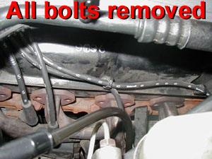
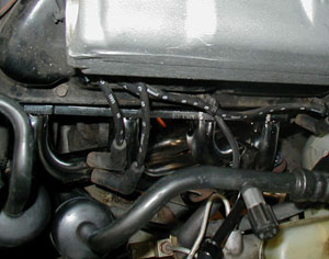
2. There are 4 bolts on the backside of the brake caliper, 2 long ones towards the sides (do NOT remove these), and 2 small ones directly in back of the caliper (see illustration). Those 2 small ones hold the caliper onto the rotor assembly. Unbolt those (15mm) and remove the caliper. You might need to decompress the caliper a bit by squeezing it up top. Pull it off, and you will see a tiny hole on the caliper, bend the coat hanger so it pulls through, and hang the caliper by a nut in the wheel well. You'll see it when you look. And make sure it doesn't interfere with the lowering of the strut and spring. (you might have to get creative with zip ties for this.)

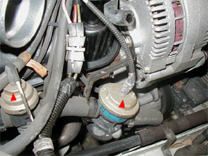
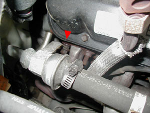
3. Remove the bolt that holds the brake hose bracket in place. (see picture) If you don't, when you lower the suspension, it will pull/stretch/screw up your lines, and that would be bad. 10mm socket for this one. Once you unbolt it, you can just let it hang down.
4. Pre-load the suspension under the A-arm about 5 inches with the floor jack.
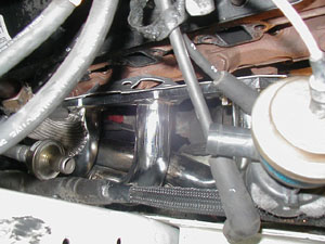
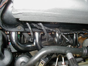
5. Sway bar (see picture). Unbolt the sway bar (15mm deep socket or open faced wrench). Remove the bolt and upper rubber bushing (remember which way the bushing was sitting).

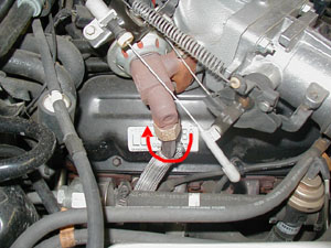
6. Tie rod end (see picture). Remove the cotter pin from the nut using a flathead screwdriver and mallet to straighten it out. Use the pliers to get a good grip on it. Then remove the nut (19mm) and set aside. If it is a newer stang, you should be able to hammer the tie rod loose by hammering on the bolt. If the rotor guard is in the way, just bend it. But trust me it seems like it won't come loose, keep hammering. It will. Once you pop it loose, swing it out of the way.
7. Strut. Remove the 3 bolts on the strut tower to remove strut. (see picture) (15mm) Once you have removed the bolts, GENTLY lower the jack, guiding the strut down, making sure it doesn't hit the inside of the wheel well. Now, there is a plastic/rubber lining in the wheel well. The strut may get caught up on it, just maneuver it around until it pops loose. I ended up jiggling it and pushing up on the liner to get it done. Keep lowering the jack until it won't go down anymore, taking care to have your buddy hold the strut as it's coming down. (you will hear a POP, that's the sway bar coming off of the sway bar end, dont freak. Now, the spring won't pop out YET. Once the A-arm is all the way down, use a pry bar to pop the spring out of the arm. Be careful, use a series of quick tugs and it should come out no problem.
It's possible for the strut to get hung up on the threads at the top. The first strut I did got bound somehow at the top. I giggled the strut, and it popped out and drop pretty violently. If it looks like the strut is not lowering as you lower the jack, giggle the strut before the jack is all the way down.

8. Remove the rubber isolators from the top and bottom and place them on the new springs (for the tops, I used zip-ties to keep them in place). Remember which way the pigtails are facing!!!! It will help if you spray some WD-40 on the new spring to get the bottom isolator on (snake like sheath). Worked for me.
9. Now, place spring in a-arm (shouldn't be too bad since the spring is shorter than the stocker). Have a friend hold the strut as you jack the suspension back up. Use one hand (while friend is holding strut) to jack the jack, and the other to guide the sway bar end into the sway bar. Carefully line up the holes of the strut to the tower (you may have to wrestle with the liner again, I found if you pull down on the strut to compress it, it helps). Once you got them lined up, jack it up and bolt in the strut. Don't worry about the stock strut (C&C) plates, on the newer stangs, they should be riveted in, but since you will be in need of an alignment, I wouldn't worry about them moving. The alignment shop is gonna move them for you. Bolt the strut back up at the top (15mm : 30 ft-lbs).

10. Re-install the sway bar bushing and bolt (15mm : 14 ft-lbs), then re-install the tie rod end to the tie rod (19mm : 41 ft-lbs). (don't forget the cotter pin!)
11. Take the utility knife, and scrape very carefully along the edge of the rotor where the caliper goes. Remove any rust and metal burrs that would scrape the pads. Reinstall the calipers (you may need to press the pads into the calipers to get it to sit right). Once you get it started on the rotor, the rest is easy. Then, line up the caliper bolts on the rear, and bolt 'em in (15mm : 85 ft-lbs). It helps if you are lying on your back from this one.
12. Bolt the brake hose retainer bolt back into place. (10mm)
13. Recheck to make sure everything is tight and secure. Stand up, stretch, drink a beer (better make that a couple). And go do the same to the other side!
My Dad and I performed this task in 4 hours learning as we went. If my pictures aren't helpful enough, look in the Haynes manual, they have great pictures, but I think mine will get you through the hard parts.
You will need to wait 2-3 days for the springs to settle, then go get an alignment. Trust me....you'll need one.
Good luck!!!!

The Do-it-yourself Alignment

When I first said it took $20 in tools I made a quick guess off the
top of my head, but here is what you need and a guess of the cost.

~15' of clear vinyl tubing about 5/16" diameter              $3.00
2  12" rulers - swipe from office supply at work :-)         $0.00
~10-20 pieces of fairly stiff floor tiles 12X12"
    left over from the last time you replaced kitchen floor  $2.00
16" bubble level from Roses on sale                          $3.00
Piece of wood long enough to span one wheel from lip to lip  $0.00
6" machinists ruler with 1/32" or better markings            $4.00
Carpenters Plumbob on sale at Sears                          $2.00
Some kind of fixture for measuring Caster                    $????
Fishing line - about 40 feet                                 $1.00
4 jack stands - should already have                          $0.00
Magnetic base carpenters Protractor                          $4.00

I didn't miss the $20 guess by much.

These are the minimum you need.

There are some other ones that may help. A Lucas or similiar digital
protractor is a great tool. If I were to spend much money on any one
tool it would be one of these. I think they are about $90, but if anything
is worth the money they are. They will just make the job much easier.

OK first make sure your tires all have proper air preassures in them.
First you will need to find a level spot. For this I use clear tape
and attach the two rulers to the ends of the clear vinyl tubing.
then you fill the tubing with water. I usually use the tubing like
a straw and draw the water up into the tubing. You need two people
to use this as a water level. The idea is the water will be level at
both ends of the tubing when the tubing is held upright. You can then
stand one ruler where one wheel will be and the other ruler where another
tire will be and if the water is at the same level on the two rulers
then those two spots are level. You can then adjust the "pads" where
the tires will be by making stacks of tile. Each tile is usually about
1/8" thick so it takes a few tiles to bring up all the low spots up
to the highest spot. In your garage you may want to mark these spots
and take notes of how many tiles each place needs.

Next you need to find out how true your rims are. I jack up each wheel
and sit the jack stand next to the wheel and sit the machinists ruler
on the jack stand with it extending just to the rim. Then rotate the
wheel one turn and see how much runout you have. On most alloy wheels
they will have less than 1/32" which is just fine. On factory steel
wheels some wheels may have as much as 1/4" which will ruin your
measurements. Find 2 places on your wheel that are 180 degrees apart
and have the same runout measurement. On almost all wheels there is 2
places you can use to measure on, though you may have to search for
the spot. I then mark the spots with a pencil or magic marker.

Alternatively you can either check the tire for trueness and use the
tire for measuring, or you can make chalk marks around the tire on the
edge of the tread and use a nail or something sharp to make a scribe
line around the tread surface near the outside and make all measurements
to the scribe line. To do this jack the wheel up so it can spin
freely and drive a nail through a piece of wood. Lay the piece of wood
on the floor so that the point of the nail just touches the tire tread.
When the tire is spun around you will have a true line scratched around
the tire. I have found this method of measuring to not be as convenient
as using the rim, so use the rim if it is possible. If your rims are
true you can assume them to always be true unless you run over a curb
or something. This means you don't have to check them every time you
align your car.

Next I like to find the centerline of my car. I do this by using the
plumbob draped over my inner suspension mounting points and measuring
half way between them and finding the center-line. This of course
does not work on all cars. Some cars don't have suspensions that are
mirrors of each other, but most do. I will drop the
plumbob to the floor and make pencil marks on the floor.
Then I will measure on the floor. I found a friends Corvette to have a
perfectly straight frame, but to body of the car to be about 1/2"
crooked on the frame. You can't go by the center of the bumper or
anything like this. Once you have found the C/L carry the mark
up to the chassis or body. I made a fine white line on the front of the
frame and the rear of the body under the bumper on my Mustang GT
with a paint marker. Now I measure from the centerline for all
measurements.

Now put the car on the leveled pads. It is best to have rolled the
car back and forth a few times to get the suspension settled. Also
I should mention that I have made pads out of one square foot cuts
of 2"X12" boards with small angled ramps on the fronts of them. This
lifts the car up 2" making suspension parts easier to get to. I then
level with the tiles on top of these pads. It works fairly well making
the suspension parts easier to reach.

First I like to check the castor. I seldom make any chages to this
adjustment. It is also not that critical to have exaclty to some
spec, but it is important to have each side even. For this I use the
Magnetic base protractor. It is accurate to .5 degrees which I think
is adequate for castor measurement. On a Strut car I simply place it
on the strut and measure the angle of the strut. This may be off
slightly from the spec books, bit the error is correct from side
to side and it is fairly close. If you have a car with upper ball
joints first check your spindles for a machined flat spot that is
parallel with the ball joint axis. If this exists then you can simply
place the protractor on this surface and measure castor. Many cars
have this machined surface for various reasons. If it doesn't then
all is not lost. You will need to make some sort of fixture that
will "reach in" to the ball joints. You will need a vertical flat
surface with two "arms" extending to the ball joints. A 2X4 with
2 long bolts through it may work. You want a vertical surface parallel
with the ball joint axis. You can measure this with the surface
with the protractor again. You can also measure this in a similiar
method to how I will measure camber later for more accuracy.
This is of course only necessary if your car has some way to
adjust castor, which many do not.

Next I like to measure camber. This is the most important measurement
in autocrossing in most people's opinion. I use the short level attached
to a piece of wood and the machinists ruler for this. I cut the piece
of wood so that it will span across from the top wheel lip to the
bottom one. I then attach the level to the piece of wood. I use the
wood for a couple of reasons. First I can shim between the wood and
the level to correct for errors that may occur  in the cheap level.
I have found most of them to have some small inaccuracies in them.
Also you may need to notch the wood to clear the wheel in the center
for the hub or something. I also have different lengths of wood for the
different wheel diameters I work with. To correct for errors I use the
plumbob. It will hang vertical. I then shim between the wood and the
level until it is indicating level when the board is completely
vertical.

Now you must have the two places on your wheel you found to be true
to each other, vertical (straight up and down). If your entire wheel
is true then it is a great benefit at this point. Take the piece of
wood and the level and span across your rim with the level vertical.
Now use the bubble and pull out from the top of the wheel until you
are holding the level vertical. Now measure from the piece of wood to
the top of your rim. It will be a distance of about 1/4" or so (assuming
you have negative camber. Take this measurement with the machinists ruler.
Be as accurate as you can. Then you need to take that distance and divide
it by the span distance of the piece of wood. For a 15" wheel you can
just use 15" and a 16" wheel 16" etc. Then look up this number in your
old Trig table in your high school trig book. You will need to find the
arc tangent of the number you have. The degrees of this will be the
camber angle.

I have a 10 line basic program that will print a chart for converting these
angles I have included in the end of this. I have also included a chart
that will convert this measurement without dividing and looking up the
measurement. I now prefer to keep my measurements in inches of gap at
the top of the wheel rather than converting them to degrees. I keep
my log books in this measurement rather than degrees for each car. It
only causes a problem if I change the rim diameters of any one car I
am working with.

For toe in measurement I need to reference the centerline of the car.
First you need to get the measuring points on your wheels at 9 and
3 o'clock. This is where it is helpful to have true wheels, then you
don't have to move the car. You will need the jack stands and fishing
line for this, plus the machinists ruler. you want to set up the fishing
line outside the sides of the car an equal distance from the centerline
of the car. I tie the fishing line to the jackstands so that the line
when streched will be about equal height to the center of the wheel hubs.
This does not have to be exact, but close to the wheel hub center.
measure out from the centerline to about 3" outside the wheels. The
setup will look like this when viewed from above:

   jack stands --> X--------------------------------------------X
                     ---======----------------------======----
                     |                                       |
                     |                                       |
                     |                                       |
           Car --->  |                                       |
                     |                                       |
                     |   Wheels                              |
                     |     V                                 |
                     ---======----------------------======----
                  X---------------------------------------------X
                                      /^
                         Fishing line/


It is important to get the fishing line parallel to the centerline of the
car. You can't measure to the rocker pannel or the wheel hubs or anything
initially because they may or maynot be parallel to the centerline. So the
first time measure from the centerline that you found before. Now it is good
to then measure from the bottom corners of the door or the rocker pannel
or something and record the measurement in your log book. It will make
the setup much faster of you want to change your toe quickly at an
event. It should be noted that a prefectly level pad is not necessary
for toe setting. It is good to get the car on a fairly level spot
but exactly level is not important.

Then to measure the toe measure at the front edge
of the rim and the rear edge of the rim and subtract the difference.
That will give you the toe measurement. Obviously for toe in the measurement
at the rear of the wheel (from the fishing line to the edge of the rim)
will be less than the measurement at the front of the wheel. The reverse
is true for toe out and the two measurements will be equal for zero toe.
The measurements you will be working with will actually be less than
what is usually referenced in spec books because the diameter you are
working with is the rim diameter, the measurement most cars use is taken
at the tread surface, so you may need to make some conversions depending
on the specs for your car. Find out how the specs you are working with
are measured. Some cars give angles of toe in degrees, some are inches of
toe on each side, and some are total toe added together between the sides.
Make sure you are working with apples and apples not apples and oranges.

Each time you make a toe adjustment recheck your steering wheel if you
have not locked it. When you adjust one side the steering wheel usually
moves and must be re-centered before you take new measurements. Locking
the wheel some way will make the job easier.

As you are making changes take a note of what one shim here and one turn
of the tie rod there changes and how much. You will notice that a camber
change changes the toe drastically, but as toe change does very little
to the camber, etc. When you get used to these things then changing your
toe settings as you are changing your tires at an event is a rather simple
matter and changing it back to the original toe setting when it is time
to drive home is easy if you have made a few marks. On my Mustang GT
I have marked the strut tops as to what change is what camber and I have
2 makrs on each tie rod end. I used to change the camber and toe at
each event, but I now leave the negative camber in and dial in a little
extra toe-out before an event and can feel confident about resetting
it correctly before I drive home. I check it occasionally just to make
sure the frame hasn't changed.

It takes a couple of hours the first time, but once you have done this
a couple of times you can do a complete check of your alingnment in a
couple of minutes in your garage and at an event you can locate a flat
spot and check a car completely before you run. It is really fairly easy
to do once you get used to it.


Here is the chart I promised. It goes up to 6 degrees of camber. The way
you use it is to look up the gap between the level and the rim at the
top on the diameter rim you are using and look on the left column and find
the number of degrees. I have included the tangent of the angle just for
good measure.


 deg      tan      17       16       15       14       13
-----------------------------------------------------------------------
 0.1  |  .0017   0.0297   0.0279   0.0262   0.0244   0.0227
 0.2  |  .0035   0.0593   0.0559   0.0524   0.0489   0.0454
 0.3  |  .0052   0.0890   0.0838   0.0785   0.0733   0.0681
 0.4  |  .0070   0.1187   0.1117   0.1047   0.0977   0.0908
 0.5  |  .0087   0.1484   0.1396   0.1309   0.1222   0.1134
 0.6  |  .0105   0.1780   0.1676   0.1571   0.1466   0.1361
 0.7  |  .0122   0.2077   0.1955   0.1833   0.1711   0.1588
 0.8  |  .0140   0.2374   0.2234   0.2095   0.1955   0.1815
 0.9  |  .0157   0.2671   0.2513   0.2356   0.2199   0.2042
 1.0  |  .0175   0.2967   0.2793   0.2618   0.2444   0.2269
 1.1  |  .0192   0.3264   0.3072   0.2880   0.2688   0.2496
 1.2  |  .0209   0.3561   0.3352   0.3142   0.2933   0.2723
 1.3  |  .0227   0.3858   0.3631   0.3404   0.3177   0.2950
 1.4  |  .0244   0.4155   0.3910   0.3666   0.3422   0.3177
 1.5  |  .0262   0.4452   0.4190   0.3928   0.3666   0.3404
 1.6  |  .0279   0.4749   0.4469   0.4190   0.3911   0.3631
 1.7  |  .0297   0.5045   0.4749   0.4452   0.4155   0.3858
 1.8  |  .0314   0.5342   0.5028   0.4714   0.4400   0.4085
 1.9  |  .0332   0.5639   0.5308   0.4976   0.4644   0.4313
 2.0  |  .0349   0.5937   0.5587   0.5238   0.4889   0.4540
 2.1  |  .0367   0.6234   0.5867   0.5500   0.5134   0.4767
 2.2  |  .0384   0.6531   0.6147   0.5762   0.5378   0.4994
 2.3  |  .0402   0.6828   0.6426   0.6025   0.5623   0.5221
 2.4  |  .0419   0.7125   0.6706   0.6287   0.5868   0.5449
 2.5  |  .0437   0.7422   0.6986   0.6549   0.6113   0.5676
 2.6  |  .0454   0.7720   0.7266   0.6811   0.6357   0.5903
 2.7  |  .0472   0.8017   0.7545   0.7074   0.6602   0.6131
 2.8  |  .0489   0.8314   0.7825   0.7336   0.6847   0.6358
 2.9  |  .0507   0.8612   0.8105   0.7599   0.7092   0.6586
 3.0  |  .0524   0.8909   0.8385   0.7861   0.7337   0.6813
 3.1  |  .0542   0.9207   0.8665   0.8124   0.7582   0.7041
 3.2  |  .0559   0.9504   0.8945   0.8386   0.7827   0.7268
 3.3  |  .0577   0.9802   0.9226   0.8649   0.8072   0.7496
 3.4  |  .0594   1.0100   0.9506   0.8912   0.8318   0.7723
 3.5  |  .0612   1.0398   0.9786   0.9174   0.8563   0.7951
 3.6  |  .0629   1.0695   1.0066   0.9437   0.8808   0.8179
 3.7  |  .0647   1.0993   1.0347   0.9700   0.9053   0.8407
 3.8  |  .0664   1.1291   1.0627   0.9963   0.9299   0.8635
 3.9  |  .0682   1.1589   1.0908   1.0226   0.9544   0.8863
 4.0  |  .0699   1.1888   1.1188   1.0489   0.9790   0.9090
 4.1  |  .0717   1.2186   1.1469   1.0752   1.0035   0.9319
 4.2  |  .0734   1.2484   1.1750   1.1015   1.0281   0.9547
 4.3  |  .0752   1.2782   1.2030   1.1279   1.0527   0.9775
 4.4  |  .0769   1.3081   1.2311   1.1542   1.0772   1.0003
 4.5  |  .0787   1.3379   1.2592   1.1805   1.1018   1.0231
 4.6  |  .0805   1.3678   1.2873   1.2069   1.1264   1.0460
 4.7  |  .0822   1.3977   1.3154   1.2332   1.1510   1.0688
 4.8  |  .0840   1.4275   1.3436   1.2596   1.1756   1.0916
 4.9  |  .0857   1.4574   1.3717   1.2860   1.2002   1.1145
 5.0  |  .0875   1.4873   1.3998   1.3123   1.2248   1.1374
 5.1  |  .0892   1.5172   1.4280   1.3387   1.2495   1.1602
 5.2  |  .0910   1.5471   1.4561   1.3651   1.2741   1.1831
 5.3  |  .0928   1.5770   1.4843   1.3915   1.2987   1.2060
 5.4  |  .0945   1.6070   1.5124   1.4179   1.3234   1.2289
 5.5  |  .0963   1.6369   1.5406   1.4443   1.3480   1.2518
 5.6  |  .0981   1.6669   1.5688   1.4708   1.3727   1.2747
 5.7  |  .0998   1.6968   1.5970   1.4972   1.3974   1.2976
 5.8  |  .1016   1.7268   1.6252   1.5236   1.4221   1.3205
 5.9  |  .1033   1.7568   1.6534   1.5501   1.4468   1.3434
 6.0  |  .1051   1.7868   1.6817   1.5766   1.4715   1.3664


This is a hard process to explain without hands on aids. I taught
a seminar for our sports car club on how to do this and evryone
thought it was easy after they did it a few times. I got several
phone calls the day after the seminar as everyone went home to do
it for the first time themselves, but they were all able to align
their own cars correctly.

It is realy easy to do and it gives you a great deal of confidence
in how your car was set up. I will try to answer all questions. I'm
sure I was not as clear as I would have hoped to be in some places.

Calvin
")